
Access Examples
The combination of the Stresscraft Drilling Machine and drill head array provides access to sites in complex engineering components which are not possible with more conventional hole drilling arrangements. This is demonstrated in the following examples:
Access Example - General Features:
Many engineering structures contain features which restrict access to areas where it is required to perform hole drilling to evaluate residual stress magnitudes. Such locations include pockets and surfaces immediately adjacent to raised features, where it is required for the drill head to have a narrow entry to approach the gauge


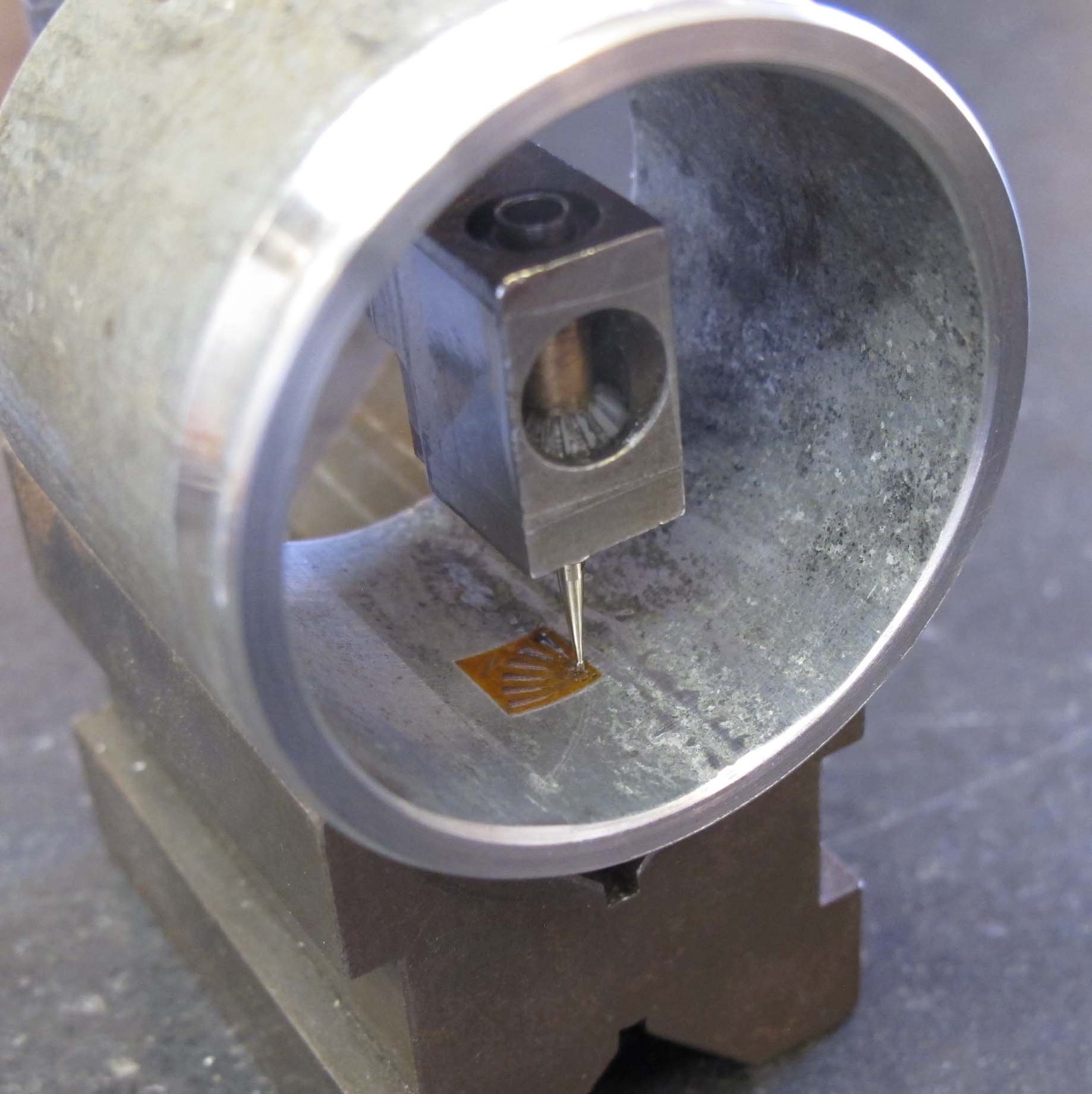
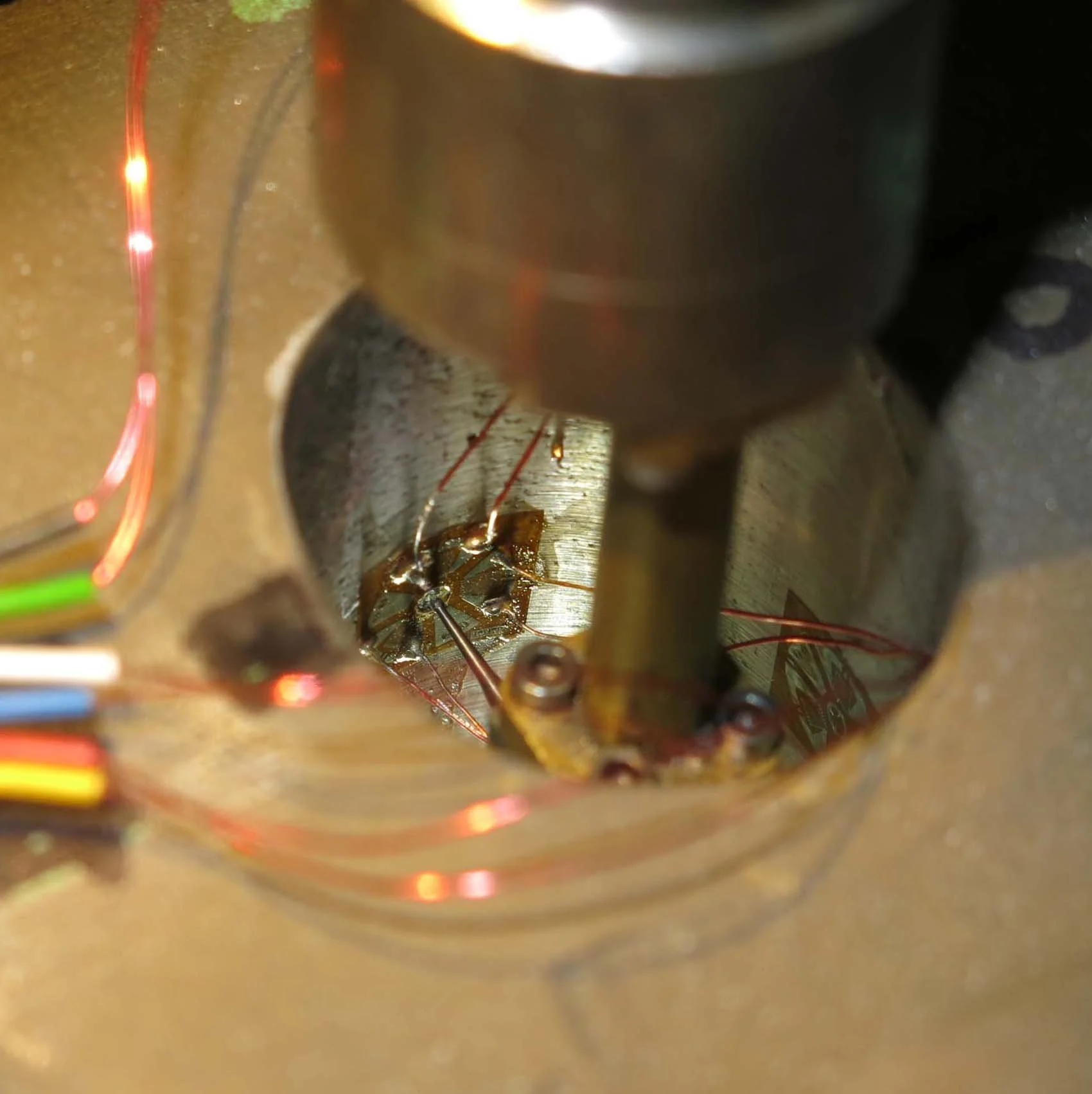
In more severe cases, where it is required to install and drill gauges within bores or cavities, or where overhanging parts of the component structure present restrictions to direct access, right-angle drill heads provide a solution. Novel means of aligning, installing and soldering gauges and methods of measuring the hole diameter are also required at such locations.


Access Example - Generic Turbine Disc:
Turbine discs usually consist of a hub, diaphragm and rim to which are connected one or more drive arms and flanges containing holes. In the example shown, the drive arms and flanges effectively mask many of the sites at (or close to) critical features of the structure, severely restricting the application of conventional hole drilling without making section cuts or machining access holes, which may have significant effects on the magnitudes and distributions of residual stresses in the remaining parts of the structure.


The use of a variety of drill heads for the various sites around the disc surface provides the freedom necessary the carry out a comprehensive and detailed assessment of residual stresses. The sites and drill head outlines shown here are a general guide to typical gauge positions but are by no means exhaustive.

Access Example: Cylinder Head:
Cylinder heads are complex cast structures with upper and lower decks containing a wide range of structural features such as ports, walls, ribs, bulkheads and bolt bosses.


Compact right-angle drill heads provide the necessary reach for working inside exhaust and inlet ports and within water jackets of larger cylinder heads. As noted for the disc example, access restrictions are not limited to the drilling process; gauge installation, drill alignment, soldering and hole diameter measurement all require special attention to ensure a successful residual stress determination.