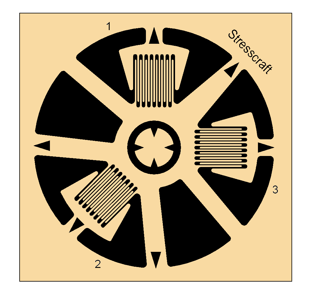
Strain gauges for centre hole drilling contain three separate gauge elements arranged around a ‘target’ which indicates where the hole is to be drilled. Two of the elements, numbered 1 and 3, are located at 0° and 90°; the number 2 element is located at either 225° or 45°, depending on the gauge type (A or B, respectively).
Strain Gauge Centre Hole Drilling

Type A Strain Gauge
Type B Strain Gauge
Preparation of the gauge site is an important aspect of gauge installation; irregular sites are smoothed to produce a surface which is acceptable for bonding without removing excessive amounts of material. The site is thoroughly degreased.
Gauges are bonded to the site using cyano-acrylate adhesive. Transparent adhesive tape is used as an installation aid for precise positioning the gauge centre and aligning with any site markings. Pressure is then applied to the gauge through the tape while the adhesive bond cures.

The target component or sample is fixed to a drilling frame or angle plate by cementing or clamping using light loads. With the component / sample position established, the strain gauge is connected to a strain indicator / recorder by soldering the lead-wires.

A PC-controlled drilling machine is fitted to the drilling frame and generally aligned to position the drill head holder over the target site. An optical head is fitted into the drill holder and adjusted to set the holder axis perpendicular to the target site. The controls on the PC screen are then used to move the cross hairs of the optical head to the centre of the gauge target.


View of gauge and graticule scale through optical head
Typical orbit path
Drilling machine with optical head
Drilling machine with straight drill head
The optical head is then removed from the drill holder. A new drill is inspected under a microscope and its diameter checked against a graticule scale. The drill is removed from the microscope and fixed into the drill head. The drill head is inserted into the drill holder to an axial position just above the gauge

Using the PC control panel command buttons, a semi-automated sequence of orbital and axial movements is performed to detect the drill depth datum while the operator observes the drill and gauge obliquely using a magnifying eyepiece. By this sequence, the drill advances by a small increment, cuts through the gauge backing material and withdraws so that the operator can view the newly revealed surface via the oblique eyepiece. When the surface datum depth is detected, the drill head is advanced to return the drill to the surface and the drill motor switched off. The strain gauge channels are balanced at this point.

The PC-controlled orbital drilling sequence is then engaged which controls the drill motor and x-, y- and z-axis control operations to complete the required sequences. The drill motor stops at each hole depth increment; after a pre-set delay strain gauge readings are recorded – this can be done manually by the operator or automatically using the USB link between the PC and strain indicator.

After completion of the final drilling increment, the drill is withdrawn from the hole and the drill head removed from its holder. The optical head is inserted into the drill holder and the drilled gauge examined for concentricity. The gauge connections are unsoldered and the gauge removed from the target site.

The hole diameter is measured using the optical head graticule scale in x- and y-directions. The average of these two measurements is used for subsequent stress computations.
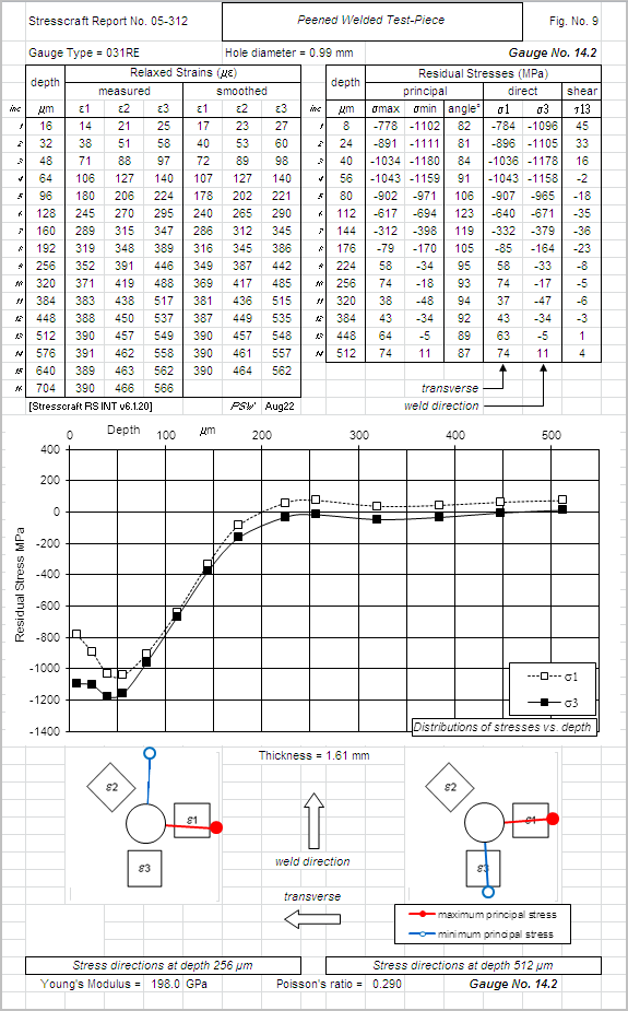
Residual stresses are computed using a spreadsheet which incorporates the Integral Method. The coefficients in the spreadsheet are based on Stresscraft finite element models for the two gauge types, for wide ranges of drilled hole diameters and component thicknesses. The test and gauge details and material properties (Young’s modulus and Poisson’s ratio) are entered into a spreadsheet file header. The measured strains, hole diameter and element orientation details are added to the spreadsheet. Data from gauges are filed to a database for incorporation into reports as individual gauge result sheets (shown here) and in summaries from groups of gauges.