
Strain Gauge Types and Selection
The selection of the strain gauge size and type is influenced by:
· the area of the available target site and the position of the gauge within that area (eg, proximity to edges, holes, raised features, etc).
· the depth to which it is required to measure stresses and the level of near-surface detail required in the final stress distribution.
Strain gauges for hole drilling are available in two configurations, Type A and Type B.

Type A: 031 size
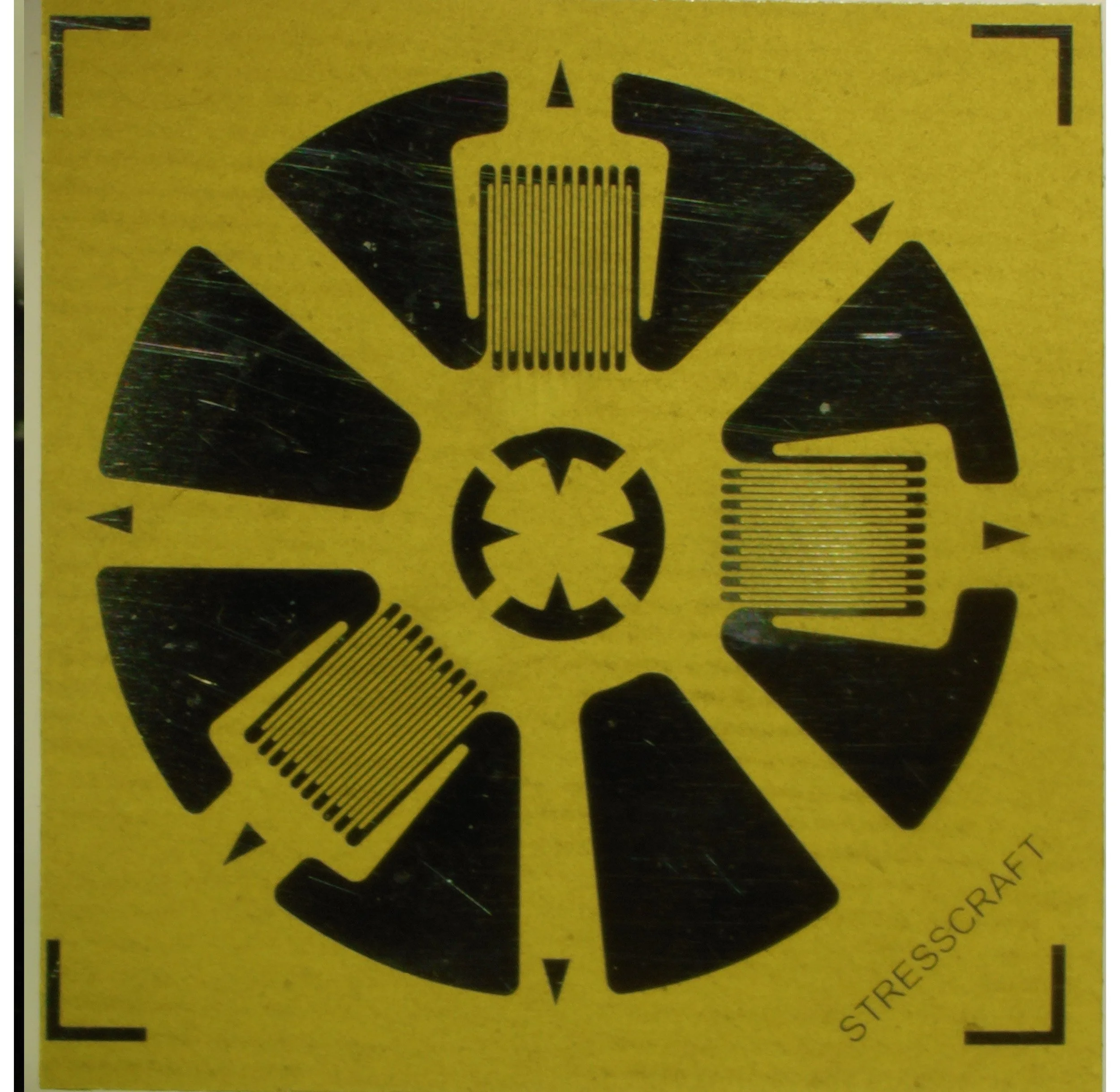
Type A: 062 size

Type B: 031 size
Each gauge contains three separate gauge elements arranged around a ‘target’ which indicates where the hole is to be drilled;. Two of the elements, numbered 1 and 3, are located at 0° and 90°, respectively, with no.1 (0°) at 12 o’clock and no.3 (90°) at 3 o’clock. For the Type A gauge, element no. 2 is located at 225° (opposite nos. 1 and 3) while for Type B, with narrower elements, no. 2 is located at 45° - directly between elements 1 and 3.
Type A gauges are suitable for applications where there are no direct constraints on the gauge position within the target site. The off-centre position of the hole within the Type B gauge area makes this gauge better suited to sites where it is required to drill the hole close to an edge, hole or raised feature (for example a weld bead).
Gauge Types A and B are both available for use with (nominally) 1 mm and 2 mm diameter drilled holes. It is common practice to identify the gauge sizes by their nominal element lengths expressed in inches x 0.001; thus, the smaller gauges (1 mm diameter drilled hole) are identified as “031- size”, while gauges drilled by 2 mm diameter holes are identified as “062-size”. Gauge Type A is also available in a larger format (“125-size”) for a 4 mm diameter hole. The gauges and their layouts, general features, solder pad positions and key dimensions are shown below:
Type B: 062 size

Gauge and installation notes :
No minimum material thickness dimensions have been listed in Table 1. Integral Method coefficients have been developed to cover section thicknesses down to 0.8 x Dh (e.g. 0.8 mm for 031-size gauges or 1.6 mm for 062-size gauges). However at section thicknesses approaching these minimum values, the maximum practical depth for stress evaluation is limited to zs max (listed above) or 50% of the section thickness (whichever is smaller). Accordingly, where a complete through-thickness stress distribution is required, this can be determined by using two gauges installed on opposing faces (offset by ~ 6 x Hd to avoid gauge-to-gauge interference). In many instances, the size of offset can be relaxed; this can be confirmed by some simple FE modelling.
Minimum widths of component edges (e.g. flanges) or channels (e.g. grooves) to which gauges can be installed can be calculated from the sum of dimensions ‘de’ and ‘de1’. For example, this sum is 5,0 mm for a 031RE gauge. The presence of edge radii or channel corner radii can affect the practicality of installations at these features.
The maximum stress data depths (zs max) that can be attained are limited by the sizes of the gauges (and the related drilled hole diameters and depths) rather than the stress calculation method.
Larger gauges (eg. 250-size, 375-size, etc) can be created by carefully bonding individual gauge elements onto the target surface which has previously been marked-out with the required alignment lines, as shown below. In this way, the maximum stress data depth can be extended to 4 mm, 6 mm, etc.


